
Magnetic Mapping of Buried Hydraulic Concrete Harbour Structures: King Herod’s Harbour, Caesarea Maritima, Israel
J.I. Boyce*, E.G. Reinhardt*, A. Raban† and M.R. Pozza
* School of Geography and Geology, McMaster University, Hamilton, ON, Canada, boycej@mcmaster.ca.
†Recanati Institute of Maritime Studies, University of Haifa, Mount Carmel, Israel.
Ψ Marine Magnetics Corporation,Richmond Hill, ON, Canada, matt@marinemagnetics.com.
Abstract
The harbour built by King Herod’s engineers at Caesarea represented a major advance in Roman harbour construction that incorporated the use of large (390 m3 ), form-filled hydraulic concrete blocks to build an extensive foundation for the harbour moles and breakwater barriers. Marine geophysical surveys were recently conducted across the submerged harbour in an attempt to map the configuration of the buried concrete foundation. A total of 107 line km of high-resolution marine magnetic surveys (nominal 15 m line separations) and bathymetry were acquired over a 1 km2 area of the submerged harbour using an Overhauser marine magnetometer, integrated DGPS and single-beam (200 KHz) echosounder. The feasibility of magnetic detection of the concrete was established before the survey by magnetic susceptibility testing of concrete core samples. All concrete samples contained appreciable amounts of fe-oxide-rich volcanic ash (‘pozzolana’) and showed uniformly high susceptibility values (κ > 10-4 cgs) when compared to harbour bottom sediments and building stones (κ < 10-6 cgs).
Magnetic surveys identify a localized increase in magnetic intensity (ca. 3-10 nT) that is attributed to the presence of hydraulic concrete within the buried harbour structure. The mapped anomaly patterns are distinctly rectilinear, indicating that the concrete foundation was laid out in ‘header’ fashion in dominantly N-S and W-E trending segments. Magnetic lows identify ‘cells’ within the concrete framework that were likely backfilled with harbour sediments prior to construction of the harbour moles and quays.
Introduction
The harbour built by King Herod’s engineers at Caesarea Maritima (Fig 1a) represented a major advance in Roman harbour construction. The marine structure incorporated the use of large (390 m3 ), form-filled hydraulic concrete blocks to build an extensive foundation for the harbour moles and breakwater barriers. The now ruined harbour covers a 10 Ha area (Fig. 1b) and lies submerged at depths of 3-9 m below present sea level.
Underwater excavations conducted at the harbour site during the last two decades have revealed a wealth of information about Roman harbour engineering and technology (Holfelder, 1988, 1997, 1999; Hillard, 1989; Oleson, 1988; Raban,1992, 1994, Raban et al. 1999). What set this harbour apart from other Roman harbours of its time was the innovative use of hydraulic concrete (a mixture of lime, volcanic ash and aggregate) to construct an extensive breakwater barrier and foundation for the harbour moles (Fig. 1b). The importance of hydraulic concrete in the construction of the harbour is well established but the extent and the detailed layout of the foundation has been more difficult to reconstruct. The foundation is well exposed at several locations on the breakwater perimeter (Fig. 1b), but over most of the harbour it is buried by up to 2 metres of littoral sediments and a thick rubble layer. The rubble layer consists of collapsed building stones, including large sandstone ashlars that pose a major obstacle for underwater excavations.
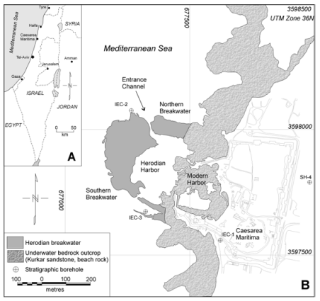
Figure 1. a) Location of study area. b) Map of the Herodian harbour showing general location of submerged breakwaters and location of modern shoreline. Location of stratigraphic boreholes also shown (after Neev et al., 1978).
In 2001, a pilot project was conducted to evaluate the use of magnetic methods for mapping the layout of the buried breakwater structures. A primary objective of the geophysical work was to evaluate whether magnetic surveys could be used to detect and map the configuration of buried concrete foundation. It was reasoned that the high content of volcanic ash and tuff within the hydraulic concrete (materials rich in magnetic oxides) should provide a sufficient magnetic contrast to allow detection and mapping with a marine magnetic survey.
In this paper we report on the preliminary results of magnetic property analysis of hydraulic concrete samples and marine geophysical survey work at Caesarea. This work demonstrates the utility of magnetic methods for mapping buried harbour structures and provides important new insights into the layout and method of construction of Herod’s harbour. Hydraulic concrete was used widely in the construction of other Roman ports (Brandon, 1996; Holfelder, 1997) and the methods reported here have broader application to investigations of other ancient harbour sites.
Methods
Magnetic property measurements
The feasibility of detecting concrete breakwater structures with magnetic surveys was evaluated before the survey work by magnetic susceptibility testing of concrete core samples. Magnetic susceptibility is a measure of the ease with which materials obtain magnetization and can be used to estimate the strength of magnetic anomaly that will be measured during a total field magnetic survey (Pozza et al., 2002). Analyses were also conducted on a variety of harbour bottom sediments, pottery (shards) and building stones, to assess the contrasts in the magnetic susceptibility of harbour bottom materials. A total of 10 concrete core samples were tested from two locations on the southern mole (site K1 and K9). In each case 5 to10 g samples of concrete were separated from the core, dried at 40°C and then disaggregated by crushing. Each sample was then weighed and its magnetic susceptibility was determined using a Bartington MS-2 meter. A calibration sample was measured following each sample run to monitor and correct for instrument drift.
Marine geophysical surveys
Marine magnetic and bathymetry surveys were acquired over a 1 km2 area of the outer harbour and the adjacent offshore area over two survey days (Fig. 2). An attempt was also made to survey the modern harbour area but was abandoned due to high magnetic gradients produced by a large sunken barge at the harbour entrance. The survey was conducted from a small Zodiac inflatable boat (Fig. 3) with N-S survey lines and W-E tie lines spaced at 10-20 m intervals (total 107 line km; Fig. 2).
Magnetic data were acquired using a marine Overhauser magnetometer (Marine Magnetics ‘SeaSPY’) (Fig. 3a) towed at a distance of 20 m behind the boat and a depth of 1-2 m. The sensor elevation was also recorded with each magnetic measurement to allow for later correction of the water depth related changes in magnetic intensity (‘drape corrections’ see below). The magnetometer was cycled at 4 Hz (0.25 s sample interval), providing better than one sample per meter at average boat speeds of 4 knots. The Overhauser magnetometer has the advantage of high sensitivity (0.015 nT) and does not suffer problems with heading errors and dead zones that complicate the use of optically-pumped alkali vapour magnetometers. Diurnal magnetic field variations were recorded continuously during the survey with a base station proton magnetometer located on the shoreline. Single-beam bathymetry data and positional data were acquired simultaneously with the magnetics using a 200 kHz echosounder and a differential GPS-chart plotting system.
The post-cruise processing of magnetic data included de-spiking to remove ferrous anomalies, diurnal and lag corrections, tie-line levelling and micro-levelling (Minty, 1991) (to remove uncompensated diurnal and systematic errors) and application of drape corrections (Pilkington and Thurston, 2001; Pozza et al., 2002). Drape corrections remove the effects of changes in sensor altitude and bottom topography and are critical because the drop off in magnetic signal amplitude is inversely proportional to the distance to the source cubed (i.e attenuation ∝ 1/r3 ). In land-based surveys, such corrections are usually not required because the sensor(s) are carried across the ground at a relatively constant height above the ground-surface. In a marine survey, however, both the bottom topography and the elevation of the sensor are constantly changing and need to be compensated. The 1/r3 fall-off in signal (or increase in amplitude, as sensor to bottom distance decreases) may in some cases, be larger than the amplitude of the signals of interest, and may introduce a significant ‘terrain effect’ in the magnetic signal. A number of schemes have been developed for removal of terrain-induced errors and are discussed in detail elsewhere (Pilkington and Thurston, 2001).
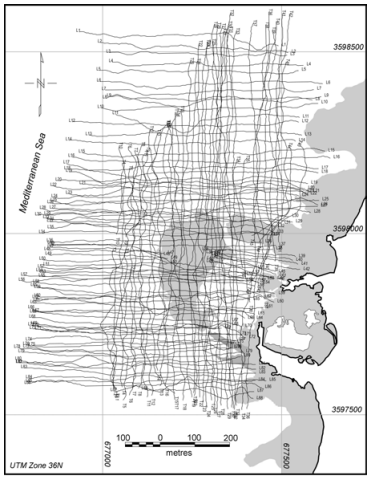
Figure 2. Magnetic survey tracklines (total 107 line km). No data were acquired within the inner harbour area due to high magnetic gradients associated with a sunken barge at modern harbour entranceway.
The fully corrected magnetic data were grided with a cell spacing of 3 m using a minimum curvature algorithm (Briggs, 1977) to generate the total field magnetic map shown in Fig. 5b. A regional residual separation of the total field data was performed by upward continuation to 50 m and subtraction of the regional field. Upward continuation is an analytical transform that yields the magnetic signal for some elevation above the original elevation at which the data was recorded. Subtraction of the upward continued signal has the effect of removing long wavelength signals associated with deep magnetic sources, thereby enhancing shorter wavelengths associated with shallow features of interest. The processing flow for the bathymetry data involved tie-line levelling (Markham, 2001), spline smoothing of profiles and minimum curvature griding of the data with a 3 m cell size.
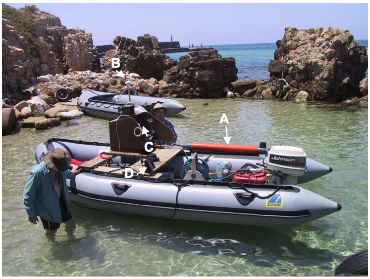
Figure 3. Zodiac inflatable boat used to collect the magnetic and bathymetric data at Caesarea. a) Marine Overhauser magnetometer (Marine Magnetics ‘ SeaSPY’), b) GPS antenna, c) Data logging computer, d) Navigation and echo sounder display.
Results
Magnetic property analysis
The hydraulic concrete samples show uniformly high magnetic susceptibilities, ranging from 1×10⁻⁴ to 1×10⁻⁵ c.g.s. The range of susceptibilities reflects variations in the content of volcanic ash and volcanic rock fragments (aggregate) added during the preparation of the concrete mixture. Analysis of the samples under a light microscope indicates that volcanic materials (ash and lithic fragments) make up 20-50% of the concrete by volume. The aggregate materials consist mainly of basalt and andesite fragments with varying amounts of local beach rock and sandstone bedrock.
The other harbour bottom materials tested show overall lower magnetic susceptibilities when compared to the hydraulic concrete. Harbour bottom sands and muds (the most abundant bottom materials) have low susceptibilities, ranging from 1×10⁻⁵ to 5×10⁻⁷ c.g.s., while the kurkar sandstone (bedrock) has an average susceptibility of about1x10-4 c.g.s. The contrast in susceptibility between concrete and harbour bottom sediments is substantial (up to 2 orders of magnitude) and results in a magnetic anomaly that can be measured with a total field magnetic survey. Calculations performed using GM-SYS™ magnetic modeling software indicate that a 25 x 25 x 5 m block of hydraulic concrete (approximate dimensions) within harbour sediments would generate a 7 nT anomaly at a distance of 5 m (field strength 45,000 nT).
Hamra sediments and pottery fragments are characterized by magnetic susceptibilities that are intermediate between the concrete and harbour bottom sediments. Some hamra samples show high susceptibility values (> 10-4 c.g.s.) owing to the high concentration of iron oxides in the paleosol layers. This suggests that hamra layers may produce significant magnetic contrasts and generate measurable magnetic anomalies.
Bathymetry
The results of the bathymetry survey are shown as a colour-contoured shaded-relief map in Figure 4a. The water depth across the harbour area varies from approximately 2 m to over 7.5 m.
The northern and southern moles and the harbour entrance channel are clearly visible in the bathymetric data and correspond well with the harbour outline previously estimated from air-photo analysis (Fig. 4. blue outline). The northern mole has a well defined rectangular structure while the southern mole has a more irregular outline and topography consisting of collapsed rubble and large ashlar blocks.
The area seaward of the harbour shows a gently sloping shelf with minor erosional channels and anomalous circular feature 150 m west of the harbour (Fig.4a. CF). The feature is approximately 100 m in diameter and has a relief of ~ 0.5 m. The feature has magnetic expression as a well-defined circular anomaly (~ 3 nT) on the total field map (Figure 4b, CF). Preliminary sediment probes conducted on the feature indicate that it may represent a concentration of ballast stones or recent dredge mound. Further work is planned to determine the origin of the feature.
Marine Magnetics
The total magnetic field map (Fig. 4b) contains anomalies from several magnetic sources. The most prominent anomaly is a broad zone of high magnetic intensity on the eastern margin of the study area. The anomaly coincides with a sandstone (kurkar) bedrock platform which forms the modern coastline. The western edge of the platform is marked by N-S trending normal fault with a downthrown western block (Mart and Perecman, 1996). Archaeologic evidence from the site suggest that neotectonic movements on the fault may have contributed to the submergence and eventual destruction of Herod’s harbour (Raban, 1992; Reinhardt and Raban, 1999).
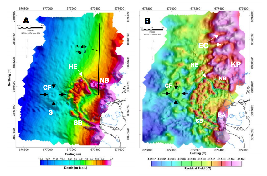
Figure 4. a) Shaded relief bathymetry map of harbour and shallow shelf. Irregular surface relief over breakwaters is due to thick rubble layer. SB = southern breakwater, NB = northern breakwater, HE = harbour entrance, S = scarp, CF = circular feature. Profile A-B (Figure 6) location shown. b) Total field magnetic map for same area. KP = kurkar platform, EC = erosional channels, BA = barge anomaly.
The buried harbour is clearly defined on the total field image and the residual magnetic field map (Figure 5a) which emphasizes contributions from near-surface magnetic sources. The localized increase in magnetic intensity (ca. 3 – 10 nT) over the breakwater areas is consistent with the presence of high magnetic susceptibility hydraulic concrete within the buried harbour foundation (Raban, 1992; Reinhardt and Raban, 1999). The anomaly patterns over the breakwater areas are distinctly rectinlinear and indicate that the concrete foundation may have been constructed in a ‘header fashion’ with concrete caissons laid out in N-S and E-W trending segments. The lows between magnetic highs can be attributed to infilling of ‘cells’ within the concrete framework with low-magnetic susceptibility materials (most likely beach sand). Figure 5b shows the preliminary interpretation of the magnetic anomalies and speculated layout of the harbour foundations. The northern mole shows a distinctly ‘cellular’ pattern of anomalies, most likely because it is located in a more sheltered position and has remained relatively intact. The southern mole shows a less coherent pattern of anomalies but a roughly rectangular framework is visible at the northern end of the breakwater segment. The southern mole, in general, has undergone more extensive undermining and collapse due to wave attack and this is reflected in the magnetic response.
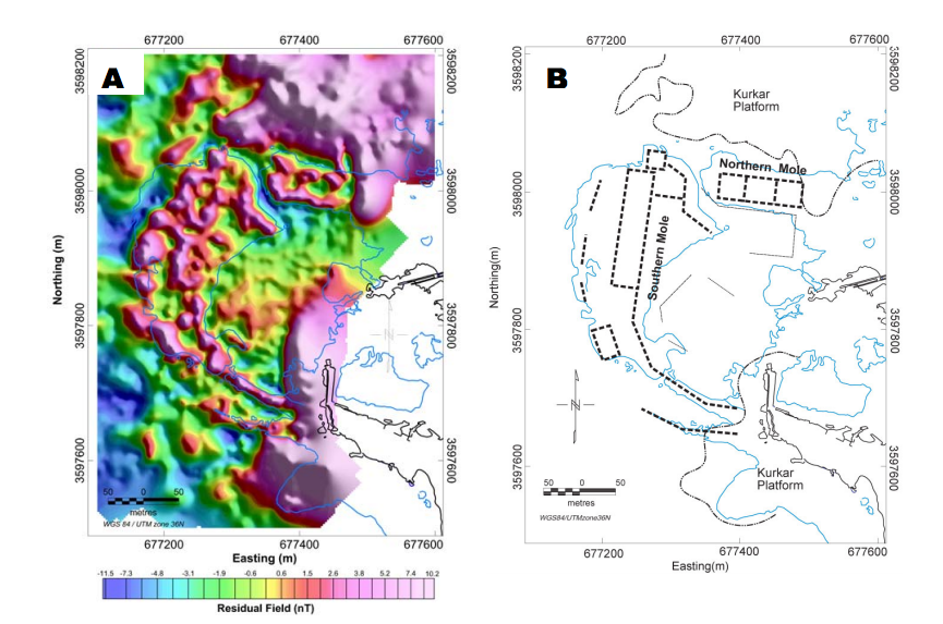
Figure 5 a) Residual magnetic field map of breakwater. Note distinct rectilinear framework’ pattern of positive magnetic anomalies separated by magnetic lows defining ‘cells’ (baffles?) within breakwater structure. SB = southern breakwater; NB = northern breakwater. b) Interpretation of magnetic lineaments; linear positive magnetic anomalies are interpreted as framework of concrete foundation blocks enclosing baffles infilled with lower susceptibility sediments (sand?).
Other interesting magnetic anomalies in the residual field map include a circular anomaly and other linear anomalies lying in the area seaward of the Herodian breakwaters. Preliminary investigations of some of these anomalies indicate that they are associated with linear concentrations of ballast stones and other building materials. These possibly record offloading of ships ballast by merchantile vessels on their approach to the harbour. The origin of these features is under currently under investigation.
Figure 6 shows magnetic and bathymetric profiles across the northern mole (location of profile shown in Figure 5a). The northern mole is indicated by double topographic peaks near the beginning of the bathymetry profile (Fig. 6a). The total magnetic field profile (Fig. 6b) clearly show double magnetic peaks directly over the mole followed by an increase in total magnetic field strength due to the buried kurkar platform. Note that the geometry of the anomalies defining the edges of the mole are repeatable and of roughly of the same width over both the southern and northern edges of the mole structure. The magnetic low between the two peaks indicates the proposed area of fill between within the concrete perimeter.
Fig. 6c is the residual magnetic field profile in which the effect of the regional magnetic field has been removed. Note the relative enhancement of the anomalies defining the mole structure, indicating a near-surface origin. In this profile it is evident that the northern edge of the mole was a slightly higher amplitude (+ 2 nT) than its southern counterpart. This may indicate that the northern perimeter of was constructed with a larger volume of concrete. To north of the breakwater area, the magnetic anomaly pattern shows undulating lows and highs which are interpreted as an erosional topography cut into the sandstone platform. The bedrock channels likely record phases of lowered sea level and subaerial erosion of the coastal platform.
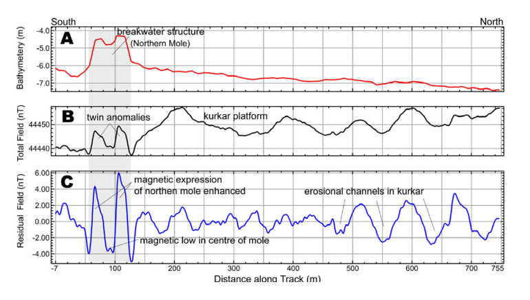
Figure 6. Magnetic and Bathymetric profiles across northern breakwater structure and Kurkar platform (Location of profile in Fig. 6a). a) Bathymetry, b) Diurnal-corrected total magnetic field, c) Residual Magnetic Field. Note twin magnetic anomalies over southern and northern edges of the breakwater structure.
Discussion and Conclusions
This study demonstrates the utility of high-resolution marine magnetic surveying for mapping a submerged and partially buried Roman harbour. Magnetic property analysis shows that hydraulic concrete materials within the harbour are of relatively high susceptibility (> 10-5 cgs) when compared to background sediments and are suitable targets for detection with a magnetic survey. The anomaly strength of the concrete structures is small (< 7 nT) when compared to the regional field generated by the local bedrock and requires careful post-cruise processing of the magnetic data. The processing steps that were most significant were removal of diurnal variations and the lag correction. Since the targets of interest are so small (3 – 10 nT), they can be easily masked by solar diurnal variations. The application of tie-line levelling (Markham, 2001; Pozza, 2002) and micro-levelling (Minty, 1991) proved effective in removing the remaining random noise due to positional errors.
High-resolution magnetic and bathymetric data were collected quickly and with minimal operational costs using a small inflatable boat, SeaSPY marine magnetometer, and integrated D-GPS/ echo sounder system (Fig. 4). Use of a small Zodiac inflatable enabled the close survey line spacing necessary for high resolution imaging of the harbour structure. The residual magnetic field map of the harbour clearly identifies the location of concrete footings and provides important new insights into the harbour construction. Further work is planned in the area seaward of the submerged harbour in order to better define the nature of magnetic anomalies associated with ballast stone concentrations.
Hydraulic concrete was used widely in the construction of other Roman ports (Brandon, 1996; Holfelder, 1997) and the methods reported here have broader application to investigations of other ancient harbour sites.
Acknowledgements
This work was supported through the Natural Science and Engineering Research Council of Canada research grants to Boyce and Reinhardt. The authors thank S. Collins and I. Psimolous for field and laboratory assistance W.A. Morris for discussions.
References
Boyce, J.I., Pozza, M. and Morris, W.A., 2001. High-resolution magnetic mapping of contaminated sediments in urbanized environments. The Leading Edge, 20: 886-890. Brandon, C., 1996. Cements, concrete, and settling barges at Sebastos: comparisons with other Roman harbor examples and the descriptions of Vitruvius, in Caesarea
Brandon, C., 1996. Cements, concrete, and settling barges at Sebastos: comparisons with other Roman harbor examples and the descriptions of Vitruvius, in Caesarea Martima: In A Retrospective After Two Millenia, edited by A. Raban and K.G. Holum, E.J. Brill, Leiden, New York, p. 25-40. Brandon, C., 1997. The Concrete-filled barges of King Herod’s harbour of Sebastos. in S. Swiney, R. Hohlfelder, H.
Brandon, C., 1997. The Concrete-filled barges of King Herod’s harbour of Sebastos. in S. Swiney, R. Hohlfelder, H. Swiny, eds., Cyprus and the Eastern Mediterranean from Prehistory to Late Antiquity. Res. Maritimae, Atlanta, Scholars Press, p. 45-58 SB Brandon, C., 1999. Pozzolana, lime, and single-mission barges (Area K), in K.
Brandon, C., 1999. Pozzolana, lime, and single-mission barges (Area K), in K. Holum, A. Raban, J. Patrich, eds., Caesarea Papers, 2. Journal of Roman Archaeology, Supplementary Series, 35, p. 169-78. Briggs, I.C., 1974. Machine contouring using minimum curvature. Geophysics. Vol. 39. p. 39-48. Hillard, T.W., 1989. A Hellenistic quay in Caesarea’s north bay. Mediterranean Archaeology, 2, p. 143-46.
Briggs, I.C., 1974. Machine contouring using minimum curvature. Geophysics. Vol. 39. p. 39-48. Hillard, T.W., 1989. A Hellenistic quay in Caesarea’s north bay. Mediterranean Archaeology, 2, p. 143-46.
Hillard, T.W., 1989. A Hellenistic quay in Caesarea’s north bay. Mediterranean Archaeology, 2, p. 143-46.
Hohfelder, R.L., 1988. Procopius, De Aedificiis, 1.11.18-20: Caesarea Maritima and the Building of Harbours in Late Antiquity. Mediterranean Historical Review, 3.
Hohlfelder, R.L., 1997. Building harbours in the Early Byzantine Era: the persistence of Roman technology. Byzantinische Forschungen, 24,p.367-80.
Hohlfelder, R. L., 1999. Building Sebastos: the Cyprus Connection. International Journal of Nautical Archaeology 28, 154-63.
Markham, K.J.,2001. Digital terrain models: analysis, comparison and integration with geophysical data. M.Sc. thesis, McMaster Univ. 173 p. Mart, Y. and Perecman, I. 1996. Neotectonic activity in Caesarea, the Mediterranean coast of central Israel. Tectonophysics, 254, p.139-153.
Mart, Y. and Perecman, I. 1996. Neotectonic activity in Caesarea, the Mediterranean coast of central Israel. Tectonophysics, 254, p.139-153.
Mart, Y. and Perecman, I. 1996. Neotectonic activity in Caesarea, the Mediterranean coast of central Israel. Tectonophysics, 254, p.139-153.
Minty, B.R.S., 1991. Simple micro-leveling for aeromagnetic data. Explr. Geophys., 22, p. 591-592. Oleson, John Peter, R.L. Hohlfelder, A. Raban, L. Vann. 1984. The Caesarea ancient
Oleson, John Peter, R.L. Hohlfelder, A. Raban, L. Vann. 1984. The Caesarea ancient harbor excavation project (C.A.H.E.P.): preliminary field report on the 1979-83 seasons. Journal of Field Archaeology, 11, p. 281-305.
Oleson, J.P., 1988. The technology of Roman harbours. International Journal of Nautical Archaeology, 17, p. 117-129. Pilkington, M. and Thurston, J.B., 2001. Draping corrections for aeromagnetic data: line- versus grid-based approaches. Exploration Geophysics, 32, p. 95-101.
Pilkington, M. and Thurston, J.B., 2001. Draping corrections for aeromagnetic data: line- versus grid-based approaches. Exploration Geophysics, 32, p. 95-101.
Pozza, M.R., Boyce, J.I. and Morris, W.A., 2003 Lake-based magnetic mapping of contaminated sediment distribution, Hamilton Harbour, Ontario, Canada. Journal of Applied Geophysics, In review.
Raban, A., 1992. Sebastos, the royal harbour at Caesarea Maritima – a short-lived giant. Int. J. Naut. Archaeol., 21, p. 111-124.
Raban, A., 1988. In search of Straton’s Tower: some additional thoughts, In R. Vann, Ed., Caesarea Papers, Thomson-Shore, Ann Arbor, p. 23-35.
Raban, A., 1994. Sebastos, the Herodian harbour of Caesarea: construction and operation. Sefunim, 8, 45-59.
Raban, A., 1991. The subsidence of Sebastos. Thracia Pontica, 4, p. 339-66.
Raban, A., Reinhardt, E.G., McGrath, M., Hodge, N., 1999 The underwater excavations, 1993-94, in Caesarea Papers 2, edited by K.G. Holum, A. Raban, and J. Patrich. Journal of Roman Archaeology, Supplementary Series No. 35. Journal of Roman Archaeology: Portsmouth, RI., . p. 152-168
Reinhardt. E.G. and Raban, A., 1999. Destruction of Herod the Great’s harbor at Caesarea Maritima, Israel – geoarchaeological evidence. Geology, 27, p. 811-814.