High-Resolution Magnetic Target Survey
By Doug Hrvoic and Matthew Pozza, Marine Magnetics
Magnetic surveying is a common methodology for small-object detection applications such as UXO clearance, pipeline location and archaeology. Now gradiometers using Overhauser technology are doing the job faster and better by directly measuring the analytic signal – a high-resolution data form that is ideal for resolving small magnetic features and eliminating the unwanted effects of geology and solar interference.
Harnessing the power of three-axis total-field magnetic gradient
Magnetometers have long been used to locate small, buried ferrometallic objects in all varieties of marine environments. Quantum total-magnetic-field sensors based on the wellknown proton or the more recent and powerful Overhauser technology have made the acquisition of stable, good quality, low-noise data relatively easy. The challenge in a target-search application is most often the interpretation of results, specifically the separation of artefacts that are not significant from the beacons that will lead a surveyor to his goals.
How We ‘See’ Objects Magnetically
A magnetometer measures the Earth’s magnetic field.A ferrometallic object is detectable by a magnetometer because it creates a magnetic field of its own that results in a local deviation in the Earth’s magnetic field. The shape of this deviation is dependent upon both the permanent and induced magnetisation of the ferrous object.The permanent magnetisation of the object may be thought of as the magnetisation acquired by the object when it was cooled from a molten state and will move and reorient with the object; it might therefore point in any direction.The induced magnetisation of the object is a result of the action of the Earth’s magnetic field on the object and is always oriented with the Earth’s field; its magnitude is a scalar function of the Earth’s field.
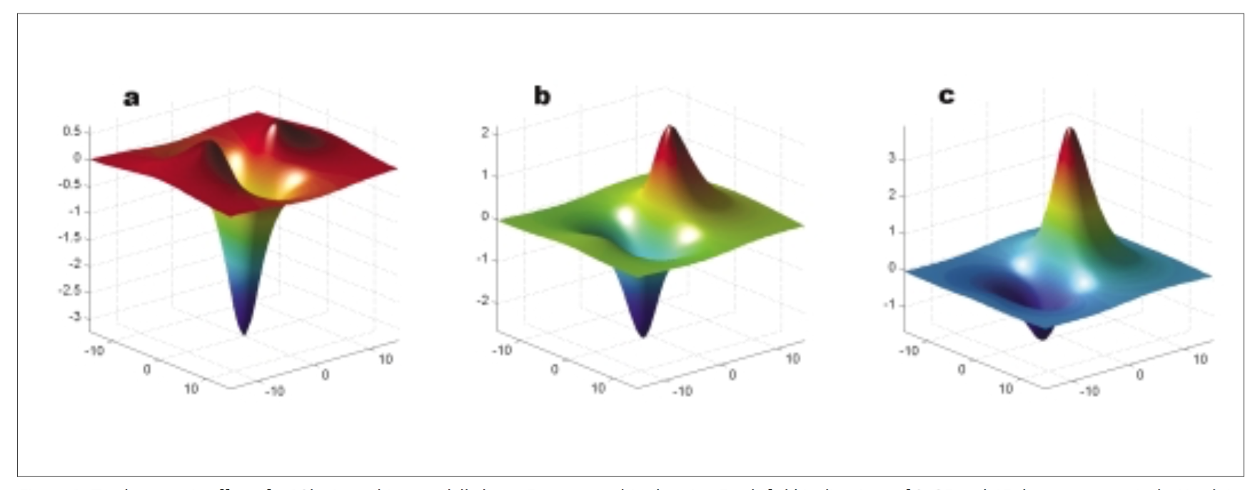
Figure 1: Total magnetic effect of a 10kg iron object modelled at a 5m survey altitude using Earth field inclinations of 0, 25 and 45 degrees respectively. North is toward the lower left. The vertical units are nT and the horizontal units are m. Target location is 0,0.
These two magnetic fields vector-add both with each other and also with the Earth’s ambient magnetic field within the space surrounding the object. This creates quite a complex mathematical combination that is complicated further by the change of the Earth’s field inclination at different latitudes. Furthermore, magnetometer surveys are conducted on relatively horizontal planes that slice through the fields we wish to detect. Consequently, the total-magnetic-field anomalies we measure are often complex in shape, even for the simplest point-source dipole.
To illustrate, Figure 1 shows 3D plots of the same point-source dipole modelled at a measurement altitude of 5m.The model takes into account induced magnetisation only, at three different Earth field inclinations of 0, 25 and 45 degrees.The Earth field inclination is a function of latitude, so the same target clearly appears different depending on where in the world it is located. Furthermore, the magnetic signal does not have a clear centre and it is not straightforward to pinpoint the target’s precise location.
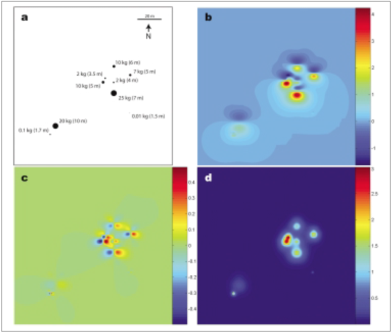
This becomes a greater problem when there are multiple small targets close enough together that their fields overlap. Figure 2a shows several iron objects of varying sizes and depths. Some of the objects are close together.The modelled magnetic map (Figure 2b) shows that the total field does not easily resolve all of the target positions; smaller and shallower targets are obscured by the magnetic response of larger and deeper objects. In the case of actual survey data, the measured total field will be complicated by ‘background’ magnetic anomalies generated by geological variations in the seabed and by temporal variation caused by solar activity.
Total-field Magnetic Gradiometers
A total-field gradiometer is a specialised type of magnetometer that measures a first spatial derivative, or gradient of the total magnetic field. The simplest gradiometer consists of two sensors separated by a fixed distance that simultaneously measure the total magnetic field. Difference in intensity is divided by distance between the sensors, giving a linear estimate of the gradient.The orientation of the axis between the sensors determines which independent component of the three-dimensional field is measured (x, y, or vertical).A well-designed gradiometer is not affected by diurnal variation (solar effects) and tends to suppress longer wavelength geological anomalies that may interfere in target mapping applications.
For decades, two-sensor gradiometers that measure a single axis of the magnetic gradient have been used. These measure a directional quantity that is dependent on their orientation in space, which frequently makes their data more, not less, complicated to interpret than total-field data.They tend to enhance magnetic structures orientated in specific directions.This is an undesirable characteristic for small-object survey.
For example, Figure 2c shows the calculated east-west magnetic gradient over the same objects calculated for the total field map in Figure 2b. Smaller and shallower targets are more easily resolved than in the total field map. However, due to the nature of horizontal gradient data, it is difficult to pinpoint the source locations. Furthermore, horizontal gradient data is still prone to anomaly distortions related to permanent magnetisation.
Figure 2: Modelled target map. a- Schematic of target sizes and locations. b- Total field map. c-Single axis gradient in east-west direction. d- Analytic signal. Colour intensity units are nT for (b) or nT/m for (c) and (d)
Three-axis Gradient – the Analytic Signal
Clearly, the magnetic gradient is a vector quantity in itself – despite the fact that it is derived from scalar (non-directional) values. The simple gradiometers described above measure only one axis of the total gradient vector at a time.To measure the entire vector, we need to measure gradient along three independent directions in 3D space.This is precisely the task for which the SeaQuest gradiometer was designed.
Once we have the entire gradient vector, we can calculate its magnitude – ignoring its direction for the moment, just as we do with total magnetic field.The result is known as the analytic signal: a data form that is used in geophysical investigations to highlight specific types of geological features. Like the single-axis gradients, the analytic signal is a higher-frequency data form than the total field. That is, it is able to resolve small targets near to each other with greater precision than total field. But, unlike the single-axis gradients, analytic signal is a completely non-directional quantity and is unaffected by the measuring platform’s orientation in space.
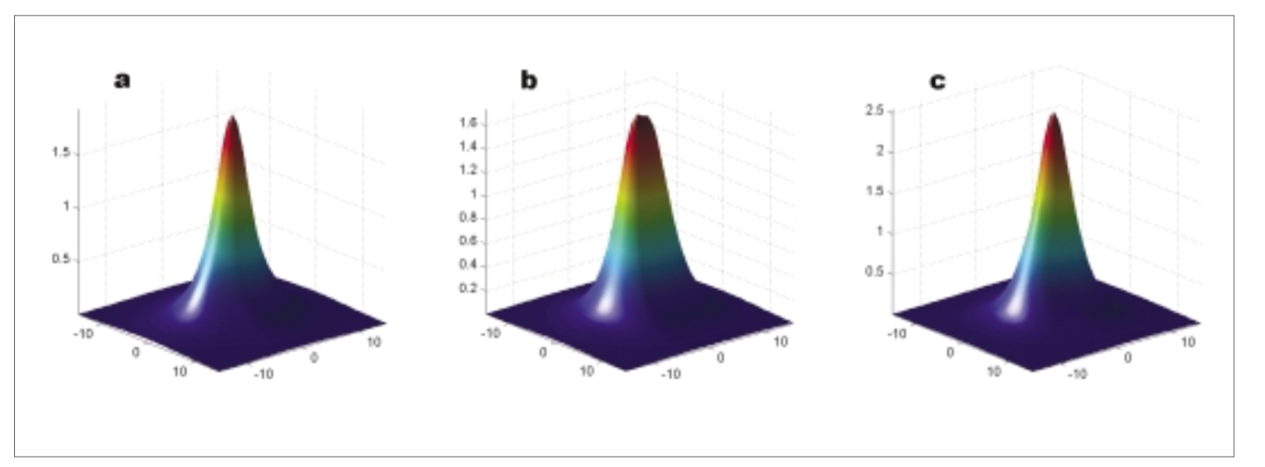
Figure 3: Analytic signal of the same object and field inclinations as in Figure 1. Vertical units are nT/m
This characteristic makes interpretation of the analytic signal very easy and intuitive. Looking back to the 10kg object we modelled in Figure 1, Figure 3 shows the same object modelled in analytic signal form at the same three Earth field inclinations.The analytic signal produces a clean, positive peak that is centred directly over the source of each target.The shape of the peak is largely unaffected by the Earth’s field inclination and also therefore by the ratio of permanent and induced magnetisation in the target.
In our modelled target field, Figure 2d shows the same objects as in 2a,b and c in analytic signal form.A clear peak marks each target. Most importantly, some small targets that were obscured in the total field by the presence of nearby large sources are now clearly visible.This last characteristic is in fact one of the most valuable features of using analytic signal.The most difficult complication in a successful small-target survey is frequently elimination of sources of geological interference. Geology typically manifests itself as large, distant anomalies that can exceed the amplitudes of the small targets by orders of magnitude in the total field.As a higher frequency data form, the analytic signal is very effective at suppressing strong, distant sources of interference while enhancing the small, nearby sources we are interested in for target search.
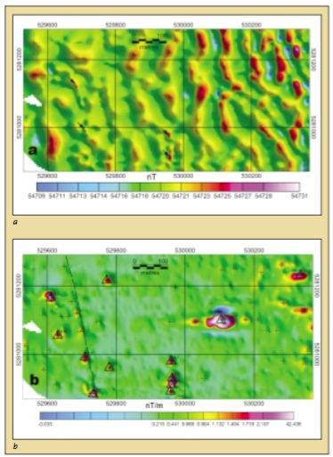
Figure 4: Field example data. a- total magnetic field map. Targets are obscured by deeper geological sources. b- Analytic signal map of same area created by gridding raw SeaQuest data. Interpreted target positions indicated by triangle symbols. Smaller targets indicated by cross-symbols
Field Example
In June 2003 a Marine Magnetics SeaQuest gradiometer was used by the US Naval Underwater Warfare Center to conduct a high-resolution survey in the inshore waters near their Keyport,Washington facility. The goal was to map the area’s man-made magnetic debris. Figure 4a shows the total magnetic field data collected by the top sensor of the gradiometer. This image represents data that would be obtainable by a conventional marine total field survey and is presented for comparison purposes.The image is dominated by sweeping anomalies related to geological variations of the seabed.This strong background magnetic response makes it difficult to quickly identify anomalies associated with ferrous objects, especially in the eastern half of the survey block. Only four potential ferrous targets in the western half of the survey site are readily identifiable (arrows).
The recorded analytic signal data is displayed in Figure 4b.The geological features are effectively suppressed.As a result, at least twelve targets are readily identifiable (triangle symbols). The interpretation of the target positions is also simplified, since all targets are expressed as ‘bulls-eye’ type positive anomalies.The most prominent feature of the analytic signal data is the large anomaly just east of the centre of the analytic signal map. Despite its large size, the anomaly is obscured by geology in the total field data. Dive teams later verified this target as a buried car.
Summary
Analytic signal is a data-form that provides superior resolution of small ferrous objects.As a higher frequency data form than total magnetic field, the analytic signal tends to enhance the effects of small nearby targets and suppress the effects of large distant sources, such as geology.This has the effect of lowering the apparent environmental ‘noise’ level in the data, allowing smaller, fainter targets to be resolved.
Analytic signal is also a simple, nondirectional quantity that identifies the location of targets with a clear peak. This makes an analytic signal map intuitive and easy to interpret – the closest thing possible to a magnetic image of the seafloor.This characteristic also makes it easy to identify targets with an automated algorithm. Marine Magnetics’ SeaQuest gradiometer is designed to directly measure the analytic signal by simultaneously measuring three magnetic gradient axes.The result is a magnetic surveying tool that provides a new standard for high-resolution small-target search.
Biographies
Doug Hrvoic is President and cofounder of Marine Magnetics Corporation.An electronic engineer by profession, he has been designing Overhauser, proton and optically pumped quantum magnetometers since 1992.
Matthew Pozza is the Marine Magnetics applications specialist. He received his MSc from McMaster University,specialising in applied geophysics. He has been conducting magnetic surveys for geophysical research and archaeological applications since 1999.


